Diagnostic printer test pages serve as essential benchmarking utilities designed to optimize hardware calibration and ensure precise print head alignment. This technical guide explains how to interpret specific patterns to evaluate nozzle integrity, CMYK color balance, and spatial resolution. By performing routine vertical and horizontal calibration, users can fine-tune ink drop placement on the substrate, effectively eliminating banding and registration errors. These procedures synchronize the internal firmware with mechanical step motors to maintain consistent ink density and mechanical throughput. Utilizing these diagnostic protocols preserves hardware longevity while ensuring professional-grade output by correcting mechanical deviations in both inkjet and laser systems.
Color Balance Evaluation
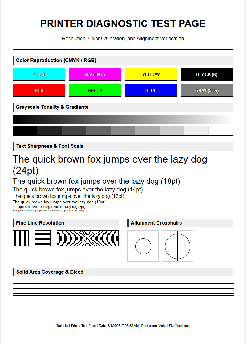
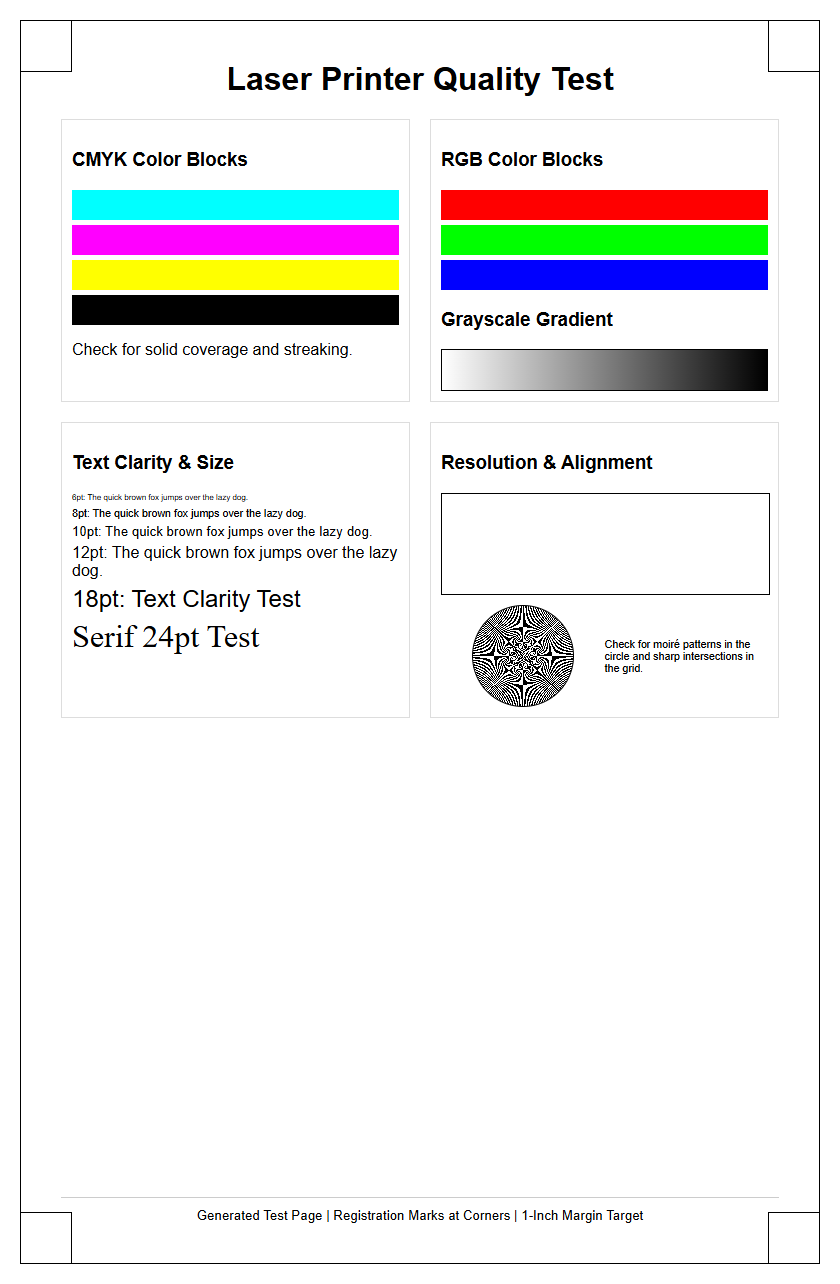
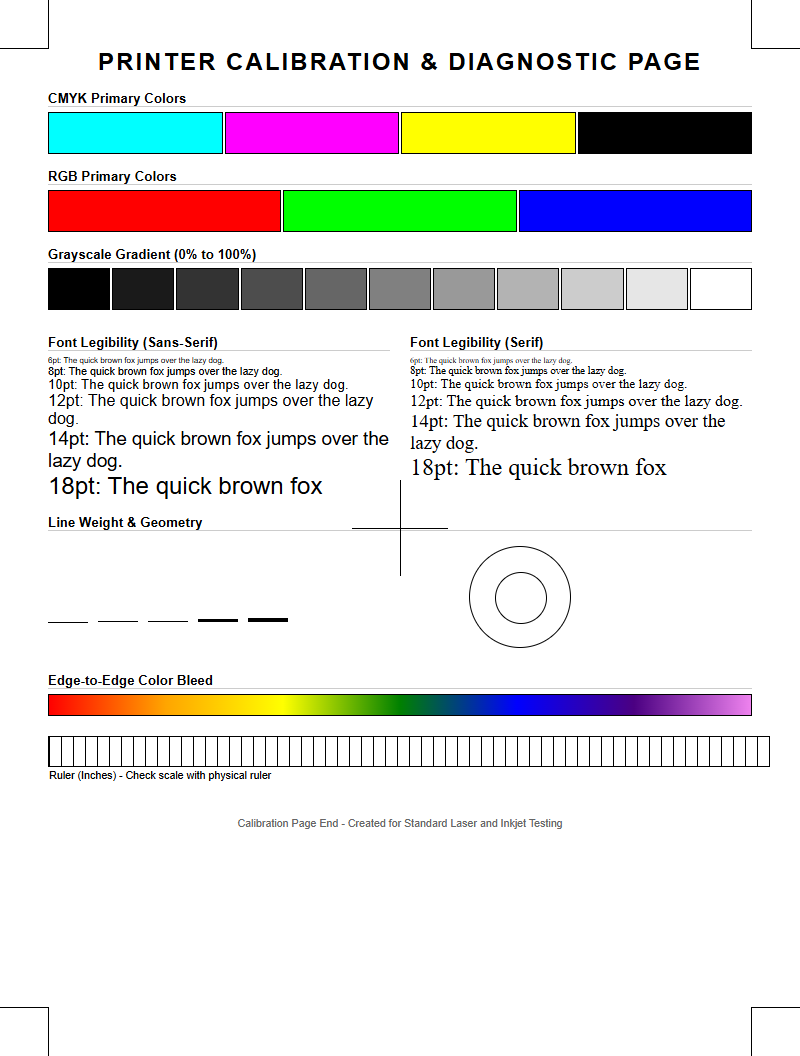
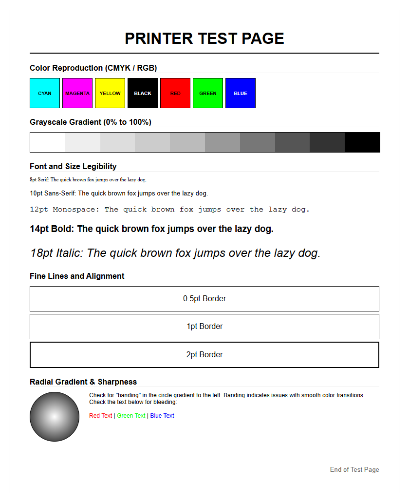
Assessing the color balance of a diagnostic printer test page is essential for ensuring that the CMYK (Cyan, Magenta, Yellow, and Key/Black) channels are synchronized. When analyzing the output, technical technicians look for a neutral gray scale, which is the most difficult range for an inkjet or laser printer to reproduce without a color cast. If the gray ramps appear slightly greenish or reddish, it indicates an imbalance in the ink density or an issue with the current ICC profile settings.
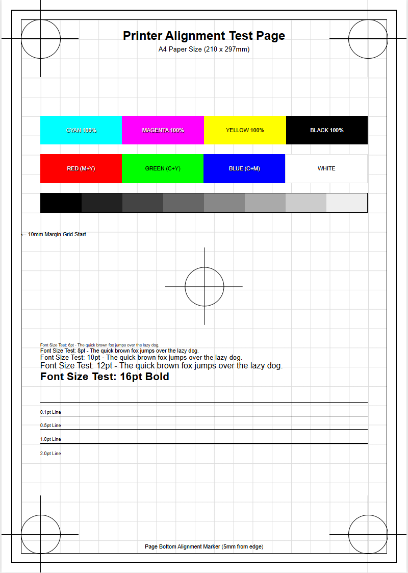
- Primary Colors: Check for pure 100% saturation without contamination.
- Secondary Overprints: Observe the mixing of RGB hues derived from CMYK bases.
- Neutrality: Ensure the gray patches do not exhibit chromatic shifts.
- Metamerism: Verify color consistency under different lighting conditions.
Achieving perfect color balance requires precise drop-on-demand firing and accurate toner deposition. A successful evaluation confirms that the printer's internal lookup tables (LUTs) are correctly interpreting digital signals into physical pigment, providing a foundation for professional-grade photo and document reproduction across various media types.
Monochrome Text Quality
Monochrome text quality focuses on the crispness of character edges and the legibility of fonts at micro-scales. A diagnostic test page typically includes text samples ranging from 2pt to 12pt fonts to evaluate the printer's native resolution and addressable DPI (Dots Per Inch). High-quality monochrome output should show no signs of "feathering" on inkjet systems or "toner scatter" on laser units. The goal is to achieve maximum contrast between the black carbon-based pigment and the white substrate.
- Examine the "serif" edges for any rounding or blurring.
- Check for consistent "leading" and "kerning" between characters.
- Verify that the internal counters of letters like 'e' and 'a' remain open and clear.
- Analyze the depth of the blacks to ensure a high Dmax value.
When text appears fuzzy or exhibits "ghosting," it often points toward an issue with the fuser assembly temperature or an incorrect voltage setting in the electrostatic transfer process. Maintaining sharp text is critical for barcode scanning accuracy and professional document archival, where fine-line definition is a non-negotiable standard for optical character recognition (OCR) software compatibility.
Print Head Alignment Verification
Print head alignment is a mechanical and electronic calibration process that ensures the print head carriage is perfectly synchronized with the paper advancement motor. On a diagnostic test page, this is usually represented by a series of overlapping lines or grids. If the vertical lines are jagged or the horizontal lines show "stepping," the printer's bidirectional alignment is likely off. This occurs when the timing of ink droplet ejection during the left-to-right pass does not match the right-to-left pass.
- Vertical Alignment: Ensures straight lines along the Y-axis.
- Horizontal Alignment: Maintains consistency across the X-axis carriage path.
- Bi-Directional Offset: Corrects timing discrepancies during high-speed printing.
- Slant Correction: Adjusts for any physical tilt in the print head installation.
Failure to calibrate alignment leads to blurry images and "soft" text. Modern printers use optical sensors to automate this, but manual verification through a test pattern remains the gold standard for high-precision work. Proper alignment ensures that every micron-sized droplet lands exactly where the raster image processor (RIP) intended.
Nozzle Clog Identification
Nozzle clogs are the most common failure point in inkjet technology, caused by dried ink or trapped air bubbles within the microscopic channels of the print head. A diagnostic nozzle check prints a "staircase" pattern for each color channel. Each individual line represents a single nozzle firing. A break in these lines signifies a "misfire" or a complete blockage that requires immediate maintenance through a cleaning cycle or a physical purge.
| Symptom | Probable Cause | Technical Fix |
|---|---|---|
| Missing Lines | Dried Pigment | Head Cleaning Cycle |
| Deflected Lines | Debris on Nozzle Plate | Wiper Blade Inspection |
| Color Mixing | Cross-Contamination | Cap Top Cleaning |
Identifying these gaps early prevents the waste of expensive substrates. Persistent clogs might indicate a failure of the piezoelectric crystals or a breach in the airtight seal of the capping station. Continuous monitoring of nozzle health is vital for maintaining the longevity of the hardware and ensuring consistent color throughput.
Ink Saturation Levels
Ink saturation refers to the maximum amount of fluid a substrate can absorb before "bleeding" or "cockling" occurs. Diagnostic pages use saturation blocks ranging from 10% to 100% density to test the limits of the media. Over-saturation leads to a loss of detail in shadow areas, while under-saturation results in washed-out colors and a lack of vibrance. This section of the test page helps in adjusting the "Total Ink Limit" within the printer driver.
- Ink Bleed: Observe if colors run into adjacent white spaces.
- Shadow Detail: Ensure dark regions aren't a solid black "mud."
- Media Compatibility: Verify the substrate can handle the fluid volume.
By analyzing these levels, users can fine-tune the ink-drop size, measured in picoliters. Proper saturation ensures the optimal balance between color brilliance and structural integrity of the paper, preventing the wavy distortion known as cockling, which can lead to catastrophic head strikes during the printing process.
Mechanical Paper Feed Check
The mechanical integrity of a printer is often revealed through its paper handling capabilities. The feed check section of a diagnostic page evaluates the precision of the pick-up rollers, the duplexing unit, and the exit rollers. Any "skew" in the print-where the image appears tilted-indicates an uneven pressure from the pinch rollers or debris in the paper path. This mechanical synchronization is critical for maintaining "registration," especially when printing double-sided documents.
- Measure the margins on all four sides for equidistant spacing.
- Look for "track marks" or indentations caused by over-tightened rollers.
- Check for "banding" caused by inconsistent stepper motor increments.
- Assess the "trailing edge" for any smudging as the paper exits the fuser.
Mechanical errors are often overlooked but can lead to frequent paper jams and hardware wear. A perfectly fed page should show no deviation from the lead edge to the trail edge. If the registration marks do not align with the physical edge of the paper, it may be time to clean the friction pads or replace worn-out rubber tires on the feed assembly.
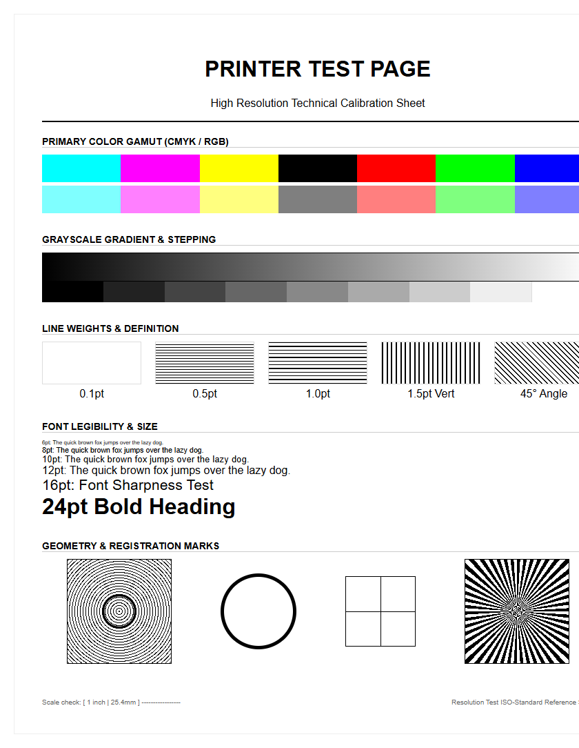
Resolution Detail Accuracy
Resolution detail accuracy measures the printer's ability to render fine lines and micro-stochastic patterns without aliasing or moiré effects. This is usually tested using "radial sunbursts" or "line pairs" that get progressively closer together. The point at which the lines merge into a solid gray mass determines the true optical resolution of the device. This test bypasses software interpolation to show the raw capability of the hardware's firing frequency and dot placement.
- Line Pair Resolution: Measures the distinctness of parallel lines.
- Concentric Circles: Detects jitter in the carriage movement.
- Micro-Printing: Evaluates the legibility of sub-1pt characters.
- Dithering Patterns: Checks how the printer simulates tones.
High resolution is paramount for architectural blueprints, medical imaging, and high-end photography. If the detail accuracy is low, it suggests a mismatch between the input file's PPI (Pixels Per Inch) and the printer's native DPI. Calibration of the rasterizer and ensuring the use of high-bandwidth cables can often resolve data bottlenecks that cause resolution degradation.
Gradient Transition Smoothness
Gradient smoothness, or "vignetting," tests the printer's ability to transition between colors without visible "banding" or "posterization." A diagnostic page features long ramps of color transitioning from 0% to 100%. In a healthy printer, these transitions should look like a continuous flow. Steps or distinct lines within the gradient suggest a problem with the bit-depth processing or a limitation in the halftoning algorithm used by the driver.
| Issue | Visual Indicator | Technical Source |
|---|---|---|
| Banding | Horizontal/Vertical Strips | Feed Timing/Clogged Nozzle |
| Posterization | Blocky Color Jumps | Low Bit-Depth/Data Loss |
| Graininess | Visible Ink Dots | Incorrect Dithering Method |
Achieving smooth transitions is vital for skin tones and sky gradients in photography. If the gradients appear "steppy," it may require an update to the firmware or a shift to a higher-quality print setting that utilizes more complex screening patterns. Ensuring the use of 16-bit data paths rather than 8-bit can also significantly enhance transition fluidness.
Common Streak Troubleshooting
Streaks on a test page serve as a roadmap for internal hardware diagnostics. Vertical white streaks usually indicate a blocked laser path or a "void" in the developer unit, whereas dark vertical lines are often the result of a scratched organic photo-conductor (OPC) drum or a faulty cleaning blade. On inkjet systems, horizontal streaks are almost exclusively tied to nozzle health or paper feed increments. Identifying the direction and frequency of the streaks is the first step in pinpointing the failing component.
- Repetitive Defects: Calculate the distance between marks to find the failing roller circumference.
- Smears: Check the fuser for toner buildup or the waste ink pad for saturation.
- Light Prints: Indicates low developer density or a failing corona wire.
Using a diagnostic page to isolate these artifacts saves time and prevents unnecessary replacement of expensive consumables. By measuring the "pitch" of the streak, technicians can use the printer's service manual to identify which specific internal gear or belt is malfunctioning, leading to a much higher first-time fix rate during maintenance intervals.
System Calibration Standards
System calibration ensures that the printer adheres to global standards like ISO 12647 or GRACoL. The diagnostic page acts as a "fingerprint" of the printer's current state. By scanning these pages with a spectrophotometer, users can generate new ICC profiles that compensate for environmental factors like humidity and temperature, which affect how ink interacts with paper. Calibration is not a one-time event but a continuous process of maintaining color consistency across a fleet of devices.
- Print the target chart using "No Color Management" settings.
- Measure patches using a colorimeter or spectrophotometer.
- Compare Delta E values to determine the variance from the standard.
- Adjust the linearization curves to normalize the output.
Standardization is the bridge between digital design and physical reality. Without it, the "What You See Is What You Get" (WYSIWYG) workflow fails. A well-calibrated system reduces waste, ensures brand color accuracy, and provides a reliable baseline for professional workflows in the commercial printing industry, where precision is the ultimate performance metric.

Comments