A printer diagnostic report serves as a comprehensive health check for your imaging hardware, offering critical insights into its internal mechanical state. By initiating a nozzle check, you can identify localized clogging within the CMYK channels, ensuring consistent ink delivery across the printhead. Simultaneously, printhead alignment data confirms precise calibration, correcting issues like banding or skewed lines by synchronizing droplet placement. Finally, system status metrics provide a deep dive into firmware versions, total page counts, and connectivity stability. Mastering these technical indicators allows for proactive maintenance, optimizing output quality and extending the operational lifespan of your device.
Interpreting Printer Diagnostic Results
Interpreting a printer diagnostic report requires a systematic approach to decoding the raw data generated by the device firmware. This internal document serves as a comprehensive health check, listing essential parameters such as the unique MAC address, current IP configuration via DHCP, and the total lifetime page count. By reviewing the report, technicians can identify the specific firmware version and determine if any recent updates have altered the raster image processor (RIP) settings. The diagnostic output often displays the current status of connectivity modules, including signal strength for wireless chipsets and hardware handshake protocols for wired Ethernet connections. Understanding these metrics is vital for troubleshooting communication bottlenecks that might impede the spooling of high-resolution graphic files. Furthermore, the report provides a detailed log of recent error codes, which can range from minor sensor obstructions to critical motor failures. Analyzing this data allows for a proactive maintenance strategy, ensuring that hardware limitations are addressed before they impact production quality or cause unexpected downtime in a professional environment.
- Device ID: Unique hardware identifier for network integration.
- Firmware Revision: Current operating system version controlling the print engine.
- Usage Counters: Total impressions across monochrome and color channels.
- Error Log: History of mechanical and software-based interrupts.
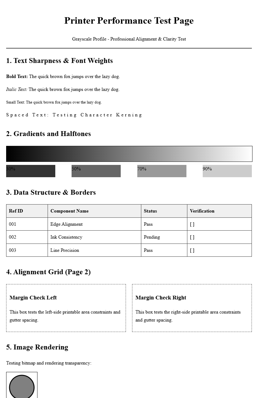
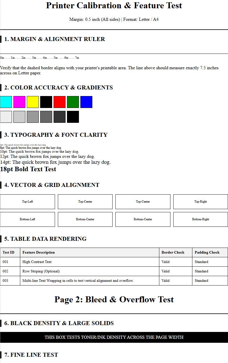
Analyzing Color Accuracy and Gradients
Color accuracy is determined by the printer's ability to translate digital RGB data into physical CMYK ink droplets. A diagnostic page typically features a series of gradient ramps that test the smooth transition between different saturation levels. Analyzing these gradients helps in identifying issues with halftoning and dithering algorithms, which are responsible for creating the illusion of continuous tone. If the transitions appear "steppy" or exhibit harsh breaks, it indicates a calibration error within the color management system. Technicians use these patterns to verify that the ICC profiles are correctly mapping the color gamut to the specific media being used. Table-based color patches are often included to check for color shifts, where one primary color might be overrepresented due to an ink delivery imbalance.
| Color Channel | Target Outcome | Failure Symptom |
|---|---|---|
| Cyan / Magenta | Smooth 0-100% ramp | Visible banding or contouring |
| Yellow | High brightness, no tint | Contamination from Black/Cyan |
| Key (Black) | Neutral, deep density | Brownish or grayish cast |
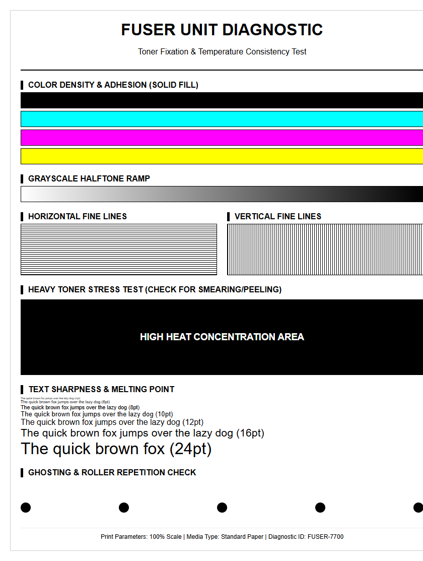
Identifying Nozzle Clogging Issues
Nozzle clogging is a common phenomenon in inkjet systems where dried ink or air bubbles obstruct the microscopic apertures of the print head. A diagnostic nozzle check pattern consists of hundreds of tiny diagonal or horizontal lines, each corresponding to an individual nozzle. If the pattern shows gaps or "missing steps," it confirms that certain nozzles are not firing correctly. This can lead to streaks or missing colors in the final output. The diagnostic report helps distinguish between a temporary clog and a permanent hardware failure of the piezoelectric or thermal elements. Regular maintenance cycles, such as head cleaning or "purging," are usually required when more than 5% of the nozzles show deficiency. Persistent gaps in the same location across multiple tests often indicate physical damage to the nozzle plate or a depleted ink damper that is preventing consistent fluid flow to the manifold.
- Nozzle Map: Visual representation of every firing element.
- Deflection: Misdirected droplets causing "fuzzy" line edges.
- Dropout: Complete absence of ink from specific nozzle clusters.
- Air Pockets: Temporary blockages caused by ink changes or idle time.
Verifying Print Head Alignment
Proper print head alignment is essential for ensuring that ink droplets land precisely where the raster image processor intends. This process involves calibrating both the horizontal and vertical axes, as well as the bidirectional timing of the carriage movement. When a printer is out of alignment, the diagnostic page will show skewed lines or overlapping patterns in the registration marks. To verify alignment, the user must examine specific numbered patterns and select the one where the lines are most perfectly centered. Misalignment often results in "ghosting" or blurred text, where characters appear to have a double edge. This is particularly noticeable in high-speed draft modes where the print head fires while moving in both directions. Proper calibration ensures the micro-stepping motor and the encoder strip are synchronized, providing a cohesive image without the staggered appearance often seen in uncalibrated machines.
- Print the alignment test sheet from the maintenance menu.
- Examine the vertical bars for any zig-zag patterns or offsets.
- Review horizontal blocks to ensure the carriage speed matches the media feed.
- Input the corresponding calibration values into the printer interface.
- Re-run the test to confirm the registration marks are perfectly flush.
Evaluating Font Sharpness and Clarity
Font sharpness is a primary indicator of a printer's effective resolution, measured in dots per inch (DPI). The diagnostic page includes text samples ranging from large headers down to 4-point microscopic fonts to test the limits of the rendering engine. High-quality output should demonstrate crisp edge definition without "bleeding" or "spidering" into the paper fibers. For laser printers, this evaluates the precision of the laser scanner and the consistency of the toner fusion process. In inkjet systems, it tests the drop-on-demand accuracy. Serifs on small fonts should be distinct and not rounded off, while the "counters" (the holes in letters like 'e' or 'a') must remain open and clear. If text appears bolded or smudged, it may indicate a problem with the fuser temperature in laser models or excessive ink saturation in inkjet models. Evaluating these samples allows users to determine if the current driver settings are optimized for professional-grade document production.
Grayscale and Black Density Standards
Achieving a true neutral grayscale is one of the most difficult tasks for any printer. The diagnostic report uses a grayscale step wedge to evaluate the "Dmax," which is the maximum optical density the printer can achieve. A high Dmax results in rich, deep blacks that provide necessary contrast for both text and images. If the grayscale patches show a color cast-such as a slight green or purple tint-it indicates that the printer is using a "composite black" (mixing CMY) rather than the dedicated black (K) channel. This phenomenon, known as metamerism, can affect the professional look of monochrome photography. The density check also reveals if the halftone screen is consistent; unevenness in the gray blocks suggests that the toner distribution or ink spray is fluctuating. Maintaining these standards is crucial for technical drawings and archival prints where tonal accuracy is non-negotiable.
| Density Level | Visual Expectation | Technical Requirement |
|---|---|---|
| Highlights (5-10%) | Barely visible dots | No harsh cutoff or "blown" whites |
| Midtones (50%) | Neutral gray balance | Balanced dot gain across all channels |
| Shadows (90-100%) | Deep, saturated black | High Dmax without loss of detail |
Detecting Smudging and Banding Patterns
Mechanical inconsistencies often manifest as banding or smudging on the diagnostic page. Banding typically appears as horizontal or vertical lines running across the page, caused by a mismatch between the print head movement and the media feed rate. Horizontal banding is often related to "stepping" errors in the paper advance motor, while vertical banding may suggest a dirty encoder strip or a scratch on the drum in laser printers. Smudging, on the other hand, occurs when the ink does not dry fast enough or when the print head physically touches the paper surface due to "head strikes." The diagnostic patterns include large blocks of solid color which make these defects highly visible. By identifying the frequency of the bands (the distance between them), technicians can pinpoint which specific roller or gear is causing the mechanical vibration. Clean, uniform color blocks are the benchmark for a well-maintained paper path and a stable ink delivery system.
- Feed Banding: Horizontal gaps caused by inconsistent paper advancement.
- Jet Banding: Lines caused by failing or misfiring nozzle clusters.
- Scuffing: Physical marks from exit rollers or star wheels.
- Toner Scattering: Small specks around characters indicating fuser issues.
Hardware Status and Maintenance Indicators
Modern diagnostic reports provide a window into the internal sensors of the printer. This section of the report details the remaining life of consumable components, such as the maintenance tank, fuser kit, transfer belt, and pickup rollers. It also monitors the thermal status of the print head to prevent overheating during long print runs. Indicators for "waste ink" levels are critical for inkjet users, as they warn when the internal absorbent pads are nearing capacity. For laser printers, the report might show the remaining percentage of the drum unit's photoconductive coating. Keeping an eye on these maintenance indicators allows for the ordering of parts before the machine reaches its duty cycle limit. Sudden drops in component health, as logged in the history, can signal environmental issues like excessive dust or high humidity that might be shortening the hardware's lifespan.
- Consumable Life: Estimated percentage of remaining toner or ink.
- Waste Box Status: Level of the container used for cleaning cycles.
- Thermal Log: History of print head or fuser temperature spikes.
- Cycle Count: Total rotations of major mechanical assemblies.
Professional Print Output Benchmarks
To qualify as "professional grade," a printer must meet specific output benchmarks defined by industry standards such as ISO/IEC 24711. These benchmarks ensure that the diagnostic page is not just a visual tool but a quantifiable measurement of performance. Key metrics include "Delta E" values, which measure the distance between the intended color and the printed result; a lower Delta E indicates higher accuracy. Another benchmark is the "dot gain" or Tone Value Increase (TVI), which measures how much an ink dot expands upon hitting the paper. Excessive dot gain leads to muddy images and lost shadow detail. Professional diagnostic reports often include "crop marks" and "bleed areas" to test the printer's ability to handle edge-to-edge printing without artifacts. By comparing the diagnostic results against these benchmarks, users can ensure their device is capable of producing marketing materials, legal documents, or high-fidelity artwork that meets commercial expectations.
Resolving Mechanical Feed Errors
Mechanical feed errors are frequently diagnosed through the presence of "skew" or "jam" codes in the status report. Skewing occurs when the paper enters the media path at an angle, leading to crooked text and images. This is usually caused by uneven wear on the pickup rollers or a misaligned paper guide in the input tray. The diagnostic page includes border lines that should be perfectly parallel to the edges of the paper; any deviation indicates a feed issue. Additionally, "multi-feed" errors-where two sheets are pulled at once-can be traced back to a worn separation pad. The report logs the frequency of paper jams at specific points in the path, such as the duplexer or the fuser entrance. By cleaning the rollers with isopropyl alcohol or replacing the friction pads, users can resolve most feed errors without needing a full hardware overhaul.
- Check the paper guides for snugness against the media stack.
- Inspect the pickup rollers for "glazing" or smooth spots.
- Clean the internal sensors with compressed air to remove paper dust.
- Verify the media weight settings in the driver match the actual paper.
- Observe the exit path for any obstructions or damaged diverter gates.

Comments